Commercial-grade fiber optic cable installation is a controlled workflow from design to acceptance: a team plans the route, confirms the pathway, pulls and routes cable within handling limits, splices or terminates, and then tests and documents every strand to ensure the network meets the design and remains serviceable after turnover.
For a refresher on fiber basics and cable construction, review fiber optic cabling or the benefits of fiber optic cable.
- Always plan the route first to avoid rework and unnecessary signal loss.
- Protect the pathway to maintain bend radius and pull limits for all cables.
- Match fiber type and connector style to distance, optics, and density requirements.
- Clean all end faces and test with an OTDR, including insertion loss, before sign-off.
- Deliver closeout docs that match labels, fiber IDs, and test results.
This guide divides each phase into practical steps to help you identify risks early, ensure workmanship, and understand closeout requirements.
What does a fiber optic cable installation mean
“Fiber optic installation” covers the full build of a working cable plant: design, pathway planning and construction, pulling and routing, termination and splicing, testing, labeling, documentation, and handoff.
Common fiber optic build types
Inside plant vs outside plant
Inside plant (ISP) refers to fiber runs located within buildings, using support structures like trays (channels for holding cables), innerducts (small plastic tubes inside conduits for extra protection), and conduits (protective tubes for cables). Outside plant (OSP) refers to runs located outdoors, which can be ducted (placed inside protective tubes), direct buried (buried directly in the ground), or aerial (suspended on poles), with each requiring specific protection depending on exposure to moisture, temperature swings, and physical impact.
Backbone vs horizontal runs
Backbone fiber connects main distribution points such as MDF (Main Distribution Frame), IDF (Intermediate Distribution Frame), data rooms, between buildings, or between floors. Horizontal fiber refers to runs from a telecom space to endpoint devices like work areas, wireless access points, cameras, and building systems.
Single-mode vs multimode
Single-mode is for long distances and higher reach. Multimode is used for shorter distances where options fit the design.
Pre-install planning
Site survey and route design
Begin with a site walk and route plan showing endpoints, entry points, telecom spaces, and pathway options (tray, conduit, innerduct, trench). Confirm pull points, splice locations, and panel spacing.
Useful planning outputs:
- Endpoint list and rack/room IDs
- Route drawings with pathway type and pull points
- Fiber counts by segment (include growth)
- Splice and patch locations
- Draft loss budget per link
Permits, safety, and compliance
Permits depend on pathway type and jurisdiction, especially for OSP work. Safety planning must address construction hazards and fiber-specific risks: laser safety, chemical handling, and safe fiber scrap disposal.
Materials selection checklist
Cable rating:
- Use cable types rated for the environment (indoor vs outdoor) and the pathway (riser, plenum, duct, direct burial).
- Plan building-entry transitions correctly when outdoor cable enters a building.
Pathway and protection:
- Size conduit/innerduct for current needs and future adds.
- Keep fiber in dedicated ducts or trays. Avoid mixing fiber and copper in the same pathway.
Termination system:
- Match the connector type and end-face type to panels and optics to avoid incompatibility.
If you are still considering media types, compare fiber optic and copper cabling tradeoffs.
Fiber optic cable installation process
Step 1: Build the pathway
Complete trays, conduit, innerduct, pull boxes, vaults, and trench work before pulling cable. Inspect the pathway for debris and damage.
Pathway checklist:
- The path is clear, dry, and safe for pulling.
- End plugs installed after pulling into the duct/innerduct to help seal out water
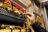
Step 2: Pulling and routing
Control pulling tension, prevent twisting, and protect the bend radius at each turn and support point.
Field rules that cut damage risk:
- Use the correct pulling method for the cable construction (do not pull on the fiber itself)
- Use figure-8 handling on long pulls to prevent twist.
- Set pull points near sharp bends and corners to reduce tension.
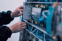
Step 3: Splicing and termination
Splicing joins fibers. Termination creates the connector interface at panels, shelves, and equipment.
Splice methods:
- Fusion splice for low-loss, permanent joints in most builds
- Mechanical splice for limited cases where speed or constraints require it
Connector basics:
- Match connector type (LC/SC, etc.) to density and equipment needs
- Match end-face type (Physical Contact [PC], Ultra Physical Contact [UPC], Angled Physical Contact [APC]) to avoid reflection and mating issues.
Step 4: Enclosures, labeling, and protection
Use enclosures and trays to protect fibers and maintain bend radius. Label every segment for future identification.
Minimum labeling set:
- Cable labels in accessible areas
- Panel port IDs that match fiber IDs
- Splice enclosure IDs and tray maps
Step 5: Cleaning and end-face basics
Dirty connectors quickly increase insertion loss. Clean before every mate, even on new installs.
Non-negotiable habits:
- Clean connectors and adapters before mating
- Keep dust caps on until the moment of connection.
Step 6: Testing and certification
Use multiple test methods and test at checkpoints, not just at the end.
Core tools:
- OTDR to locate faults, bends, breaks, and event loss
- Light source + power meter to confirm end-to-end insertion loss
- Loss budget check to confirm the link fits the optics
Recommended checkpoints:
- As-received/on the reel
- Post-pull/post-route
- Post-splice
- Post-connector
- Final acceptance
Step 7: Documentation and handoff
Closeout documentation is part of the deliverable: as-builts, labeling maps, fiber IDs, and test results per strand.
Closeout package items:
- As-built route drawings and pathway notes
- Fiber assignment and labeling schema
- OTDR traces and insertion-loss results per strand
- Splice maps and enclosure IDs
- Basic maintenance notes (what to test first, where to access)
9 common installation mistakes (and how to prevent them)
Use this as a quick checklist. For Aspen Communications’s full breakdown, see Fiber Optic Installation Mistakes and How to Prevent Them.
- Wrong connector or end-face type
- Bend radius violations at turns, trays, and slack storage
- Pulling damage from excessive tension or a poor pull setup
- Dirty end-faces and skipped cleaning steps
- Weak labeling that breaks traceability
- Skipping staged testing and only testing at the end
- Mixed fiber types or mismatched optics
- Poor protection at risers and exposed transitions
- Incomplete closeout docs that do not match the install
Request a Free Fiber Installation Estimate
If you want a commercial-grade fiber install that includes design, installation, testing, and closeout documentation, work with Aspen Communications. Request a complimentary estimate here: Free Estimate.
FAQs
How long does a commercial-grade fiber installation take?
Smaller installs can finish in days. Larger installs can take weeks. Pathway construction, access limits, and testing deliverables drive the schedule.
Single-mode vs multimode: which is right for my building or campus?
Single-mode is for longer links. Multimode suits shorter links when design limits are met.
What testing should be in the closeout package?
Ask for OTDR traces plus insertion-loss results (light source and power meter), with results reported per strand and checked against the loss budget.
What causes signal loss after installation?
Common causes include bend radius violations, dirty connectors, pulling damage, and poor terminations.
What changes in cold and snow regions?
Plan for plowing zones, freeze/thaw stress, burial depth planning, and added protection for exposed segments and risers.